Beschreibung des Vergasers
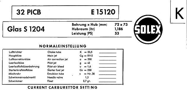
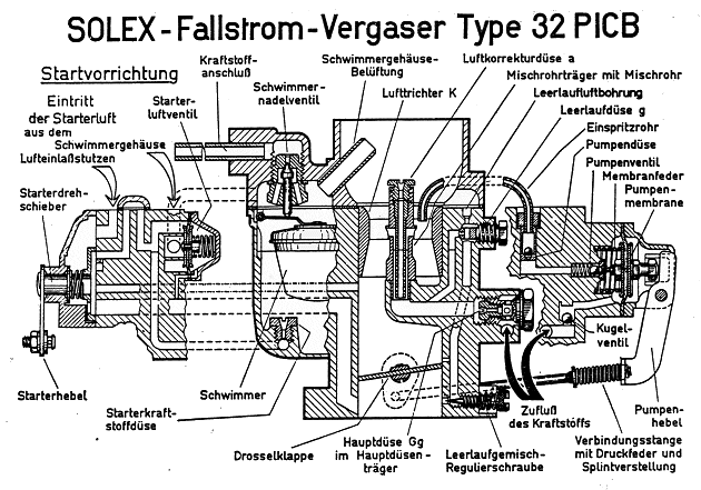
Die Vergaser der Typenreihe 32 PICB sind Fallstromvergaser mit 32 mm Saugrohrwelte, Beschleunigerpumpe und Starteinrichtung.
Als Beschleunigungspumpe dient eine mechanisch betätigte Membranpumpe, deren Membran beim Öffnen der Drosselklappe (durch Betätigung des Gaspedals) über eine Pumpendüse Kraftstoff durch das Einspritzrohr in die Mischkammer spritzt. Beim Schließen der Drosselklappe (durch Zurücknehmen des Gaspedals) saugt die Pumpe Kraftstoff in den Pumpenraum. Einspritzmenge und Einspritzbeginn sind genau eingestellt und sollen nicht verändert werden.
Die Starteinrichtung stellt einen Hilfsvergaser dar, der nach dem SOLEX-Drehschiebersystem arbeitet. Der Drehschieber wird durch den Starterknopf am Armaturenbrett betätigt und läßt eine kontinuierliche Abmagerung des kraffstoffreichen Gemisches (bei gezogenem Knopf) nach dem Start zu. Nach dem Anspringen des Motors und Eindrücken des Starterknopfes etwa auf Mittelstellung kann sofort angefahren werden. Mit zunehmender Erwärmung des Motors wird der Starterknopf allmählich bis zur Endstellung eingedrückt. Starterknopf nur bei kaltem Motor ziehen.
Montage und Wartung
Wichtig ist größte Sauberkeit, besonders aller Dichtstellen. Stets neue Dichtungen verwenden. Düsen nur durch Ausblasen oder mit nichtmetallischen Borsten reinigen. Bei nach Mög1ichkeit in jedem Frühjahr vorzunehmender Kontrolle alle Dichtungen, Gummimembranen und Schwimmernadelventil erneuern. Bei normalem Fahrbetrieb keine Veränderung der Einstellung vornehmen. Düsen und Schrauben nicht übermäßig anziehen, Luftfilter reinigen. Nur Original-Ersatzteile verwenden.
|
|
Description of Carburettor
Carburettors of the type 32 PICB series are downdrought instruments of 32 mm bore, incorporating accelerator pump and starting device.
The accelerator pump consists of a mechanicully operated diaphragm pump. When the throttle pedal is depressed, movement of the diaphragm causes fuel to be injected into the main air stream. When the throttle butterfly is closed (on allowing the throttle pedal to return), fuel is drawn into the pump cavity. The quantity of fuel injected, and the point at which injection begins, are carefully adjusted, and should not be altered.
The starting device takes the form of an auxiliary carburettor, which employs the Solex disc valve system. The disc valve Is actuated by means of the choke control on the dashboard, and after initial starting, (with the choke control fully out) it effects a progressive weakening of the rich starting mixture. When the engine has started, and the choke control has been returned approximately to the halfway position, the vehicle can be driven away without difficulty. As the engine warms up, the choke control should be moved progressively towards the "off" position. The dashboard control should be used only when starting a cold engine.
Fitting and Maintenance
Absolute cleanliness is important, particularly of all jointing taces. Always use now gaskets, and only clean the jets by blowing them out with air, or by using a nonmetallic brush. When possible, the carburettor should be checked every spring, and all washers, gaskets diaphragms and the needle valve renewed. For normal running, do not make any alteration to the setting. Do not overtighten jets and screws. Clean the airfilter. Only use genuine spare parts.
|
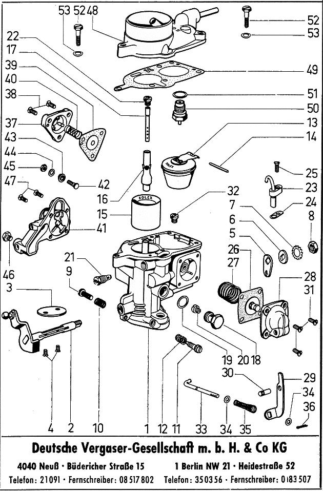
Nr
No |
Gegenstand |
Description |
V.1 | |
Bestell-Nr
Part No. |
| |
Vergaser kpl. |
carburettor compl. |
1 | |
E 15120 |
| |
Vergasergehause kpl. mont. mit Drosselhebel, Drosselklappenwelle,Drosselklappe und Linsenkopfschrauben |
body compl. with throttle lever, throttle spindle, throttle butterfly and fixing screws |
1 | |
ZK 5996 |
| 1 |
Vergasergehäuse kpl. m. eingepr. Mischrohrträger |
body compl. with pressed-in emulsion tube carrier |
1 | |
ZK 5497 |
| 2 |
Drosselklappenwelle mit Drosselhebel kpl. |
throttle spindle with throttle lever |
1 | |
ZK 5499 |
| 3 |
Drosselklappe |
throttle butterfly |
1 | |
K 10625 |
| 4 |
Linsensenkschraube |
throttle butterfly fixing screw |
2 | 2 |
K 2398 |
| 5 |
Übertragungshebel (f. mech. Ppe) |
intermediate lever for mechanical pump |
1 | |
K 11598 |
| 6 |
Unterlegscheibe |
tab washer |
1 | |
K 101 |
| 7 |
Fächerscheibe |
tab washer |
1 | |
K 5687 |
| 8 |
Sechskantmutter |
hexagon nut |
1 | |
K 724 |
| 9 |
Leerlaufeinstellschraube |
slow running adjustment screw |
1 | |
K 10792 |
| 10 |
Druckfeder (f. Leerlaufeinstellschraube) |
slow running adjustment screw spring |
1 | |
K 169 |
| 11 |
Leerlaufgemischregulierschraube |
volume control screw |
1 | |
K 10014 |
| 12 |
Druckfeder (f. Leerlaufgemischregulierschraube) |
volume control screw spring |
1 | |
K 15862 |
| 13 |
Schwimmer 5,7 gr. |
float 5.7 gr. |
1 | |
ZK 3524 |
| 14 |
Achse (f. Schwimmer) |
float fulcrum pin |
1 | |
K 10039 |
| 15 |
Lufttrichter |
choketube |
1 | |
K 10660 |
| 16 |
Mischrohrträger |
emulsion tube carrier |
1 | |
ZK 3459 |
| 17 |
Mischrohr Nr. 36 |
emulsion tube no. 36 |
1 | |
ZK 3772 |
| 18 |
Hauptdüsenträger |
main jet carrier |
1 | 1 |
K 2386 |
| 19 |
Dichtring (f.Hauptdüsenträger) |
main jet carrier washer |
1 | 1 |
K 1426 |
| 20 |
Hauptdüse |
main jet |
1 | |
K 861 |
| 21 |
Leerlaufdüse |
pilot jet |
1 | |
ZK 3016 |
| 22 |
Luftkorrekturdüse |
air correction jet |
1 | |
K 2944 |
| 23 |
Einspritzrohr kpl. niedrig |
injector Tube compl. low |
1 | |
ZK 4568 |
| 24 |
Dichtung (f. Einspritzrohr) |
gasket for injector tube |
1 | |
K 10044 |
| 25 |
Linsensenkschraube (f. Einspritzrohr) |
fixing screw for injector tube |
1 | |
K 3357 |
| 26 |
Membrane kpl. (f. Einspritzppe.) |
pump diaphragm compl. |
1 | |
ZK 3936 |
| 27 |
Membranfeder (f. Einspritzppe.) |
pump diaphragm spring |
1 | |
K 10083 |
| |
Pumpendeckel kpl. (f. Einspritzp.) |
pump cover compl. |
1 | |
ZK 4573 |
| 28 |
Pumpendeckel |
pump cover |
1 | |
K 16574 |
| 29 |
Pumpenhebel |
pump lever |
1 | |
K 10086 |
| 30 |
Achse (f. Pumpenhebel) |
pump lever spindle |
1 | |
K 10093 |
| 31 |
Linsensenkschraube (f. Einspritzpumpe) |
pump fixing screw |
4 | |
K 3357 |
| 32 |
Starterkraftstoffdüse (Leerlaufluftdüse) |
starter fuel jet (version with air correction jet) |
1 | |
K 1329 |
| |
Verbindungsstange kpl. |
pump control rod compl. |
1 | |
ZK 5513 |
| 33 |
Verbindungsstange |
pump control rod |
1 | |
K 11607 |
| 34 |
Unterlegscheibe (f. Verb.Stange) |
pump control rod washer |
1 | |
K 1318 |
| 35 |
Feder (f. Verbindungsstange) |
pump control rod spring |
1 | |
K 10088 |
| 36 |
Splint (f. Verbindungsstange) |
pump control rod split pin |
1 | |
K 10094 |
| 37 |
Ventildeckel (f. Starterluftventil) |
starter air valve cover |
1 | |
K 11000 |
| 38 |
Linsensenkschraube (f. Starterluftventil) |
starter air valve fixing screw |
3 | |
K 3357 |
| 39 |
Membrane kpl. (f. Starterluftvent.) |
diaphragm compl. for starter air valve |
1 | |
ZK 3451 |
| 40 |
Ventilfeder (f. Starterluftventil) |
starter air valve spring |
1 | |
K 10999 |
| 41 |
Starterdeckel kpl. m. Starterhebel |
starter cover compl. with strangler lever |
1 | |
ZK 5775 |
| 42 |
Klemmschraube kpl. (f. Starterhebel) |
clamp screw compl. for strangler Lever |
1 | |
ZK 99/1 |
| 43 |
Buchse |
clamping ring |
1 | |
K 1068 |
| 44 |
Unterlegscheibe |
Washer |
1 | |
K 1318 |
| 45 |
Sechskantmutter |
cable clamp nut |
1 | |
K 882/1 |
| 46 |
Klemmschraube (f. Starterzugspirale) |
strangler cable locking screw |
1 | |
K 2928 |
| 47 |
Linsensenkschr. (f. Starterdeckel) |
starter cover fixing screw |
4 | |
K 18804 |
| 48 |
Vergaserdeckel kpl. |
float chamber cover compl. |
| 1 |
ZK 55O1 |
| 49 |
Dichtung (f. Vergaserdeckel) |
float chamber cover gasket |
1 | |
K 11609 |
| 50 |
Schwimmernadelventil 1.5 mm |
float needle valve 1.5 mm |
1 | |
ZK 8811 |
| 51 |
Dichtring (f.Schwimmernadelvent.) |
float needle valve washer |
1 | |
K 11/1.5 |
| 52 |
Demontierschraube |
float chamber cover fixing screw |
3 | |
K 11610 |
| 53 |
Federscheibe (f. Demontierschr.) |
spring washer for assembly screw |
3 | |
K 2550 |


